Difference between revisions of "User:Tohline/2DStructure/ToroidalCoordinateIntegrationLimits"
(→Preamble: Begin text discussion of objective) |
|||
| Line 9: | Line 9: | ||
==Preamble== | ==Preamble== | ||
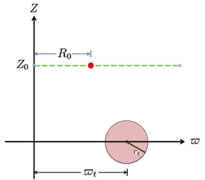
Referencing the illustration displayed in the left-hand panel of the following figure, our goal is to determine the gravitational potential at any cylindrical-coordinate location <math>~(R_0, Z_0)</math> due to a uniform-density circular torus whose major radius is <math>~\varpi_t</math> and whose cross-sectional radius is <math>~r_t</math>. | |||
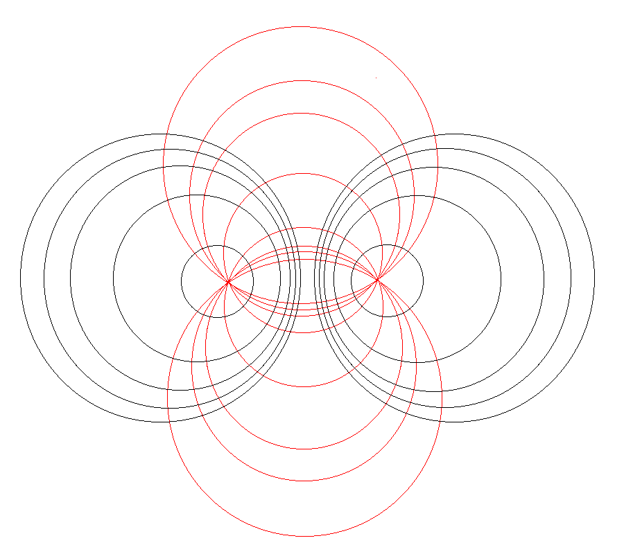
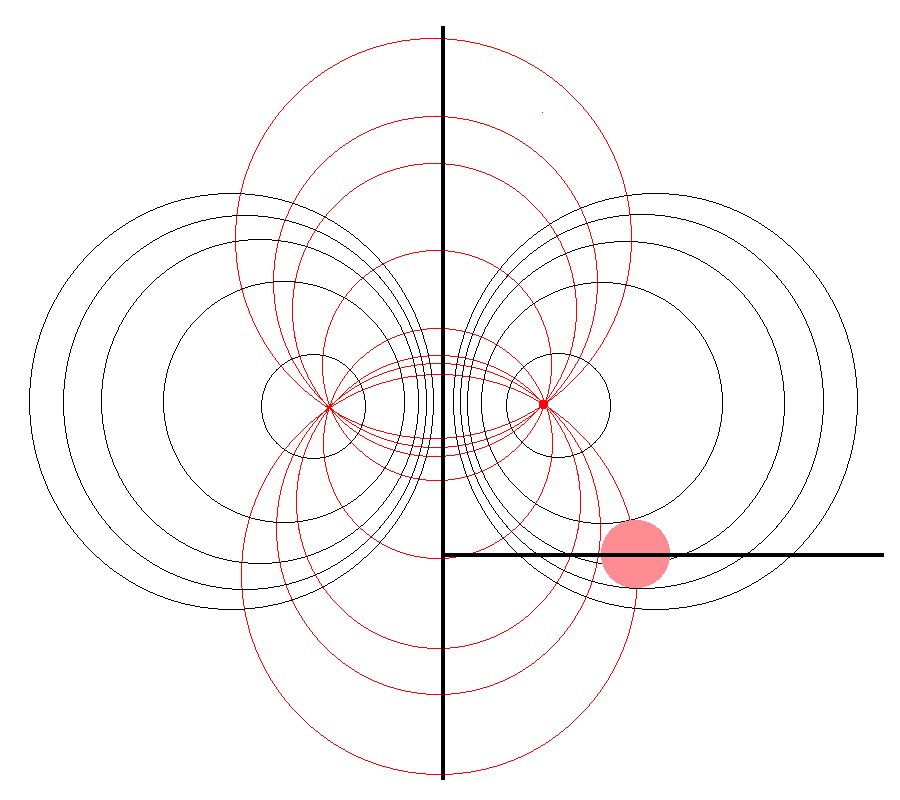
Here we explain how a toroidal coordinate system — as defined, for example, by MF53 (see the schematic illustration in the right-hand panel of the following figure) — can be used to reduce the geometric complexity of this problem. In particular, we show how the three-dimensional integral over the mass distribution can be reduced to the sum of a small number (1 - 4) of one-dimensional integrals over the <math>~\xi_1</math> "radial" coordinate in toroidal coordinates. | |||
<table border="1" cellpadding="8" align="center"> | <table border="1" cellpadding="8" align="center"> | ||
<tr> | <tr> | ||
<th align="center" colspan="2"><font size="+1"> | <th align="center" colspan="3"><font size="+1">Figure 1: Meridional slice through …</font></th> | ||
</tr> | |||
<tr> | |||
<th align="center" colspan="1"><font size="+1">(Pink) Circular Torus</font></th> | |||
<th align="center" colspan="2"><font size="+1">Toroidal Coordinate System (schematic)</font><p></p> | |||
(see also [https://en.wikipedia.org/wiki/File:Apollonian_circles.svg Wikipedia's Apollonian Circles])</th> | (see also [https://en.wikipedia.org/wiki/File:Apollonian_circles.svg Wikipedia's Apollonian Circles])</th> | ||
</tr> | </tr> | ||
<tr> | <tr> | ||
<td align="center"> | |||
[[File:SimpleTorusIllustration.png|300px|Torus Illustration]] | |||
</td> | |||
<td align="center"> | <td align="center"> | ||
[[File:Apollonian_myway4.png|300px|Apollonian Circles]] | [[File:Apollonian_myway4.png|300px|Apollonian Circles]] | ||
| Line 24: | Line 33: | ||
</tr> | </tr> | ||
<tr> | <tr> | ||
<th align="center" colspan=" | <th align="center" colspan="3"><font size="+1">Quantitative Illustration of Employed Toroidal Coordinate System</font></th> | ||
</tr> | </tr> | ||
<tr> | <tr> | ||
| Line 33: | Line 42: | ||
[[File:ConstantXi2.png|300px|Diagram of Torus and xi_2-constant Toroidal Coordinate curve]] | [[File:ConstantXi2.png|300px|Diagram of Torus and xi_2-constant Toroidal Coordinate curve]] | ||
</td> | </td> | ||
<td align="center"> | |||
| |||
</td> | |||
</tr> | </tr> | ||
</table> | </table> | ||
Revision as of 23:47, 10 November 2015
Toroidal-Coordinate Integration Limits
In support of our accompanying discussion of the gravitational potential of a uniform-density circular torus, here we explain in detail what limits of integration must be specified in order to accurately determine the volume — and, hence also the total mass — of such a torus using toroidal coordinates.

|
|---|
| | Tiled Menu | Tables of Content | Banner Video | Tohline Home Page | |
Preamble
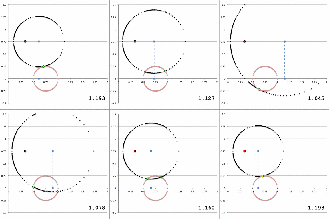
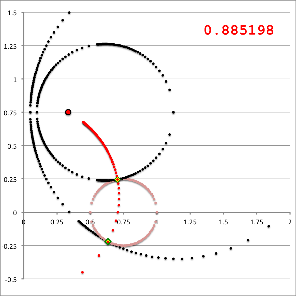
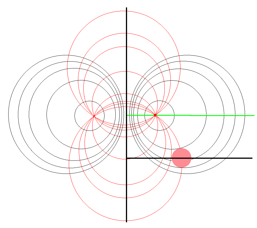
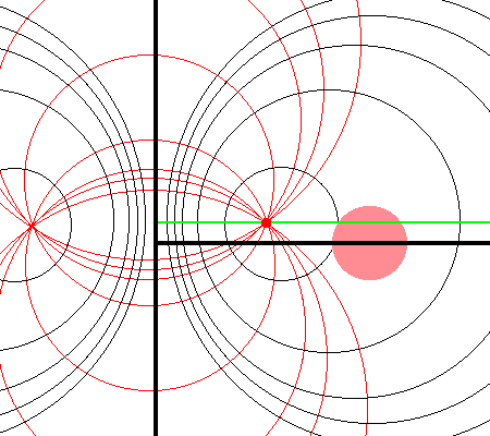
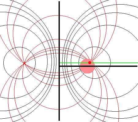
Referencing the illustration displayed in the left-hand panel of the following figure, our goal is to determine the gravitational potential at any cylindrical-coordinate location <math>~(R_0, Z_0)</math> due to a uniform-density circular torus whose major radius is <math>~\varpi_t</math> and whose cross-sectional radius is <math>~r_t</math>. Here we explain how a toroidal coordinate system — as defined, for example, by MF53 (see the schematic illustration in the right-hand panel of the following figure) — can be used to reduce the geometric complexity of this problem. In particular, we show how the three-dimensional integral over the mass distribution can be reduced to the sum of a small number (1 - 4) of one-dimensional integrals over the <math>~\xi_1</math> "radial" coordinate in toroidal coordinates.
| Figure 1: Meridional slice through … | ||
|---|---|---|
| (Pink) Circular Torus | Toroidal Coordinate System (schematic) (see also Wikipedia's Apollonian Circles) | |
| Quantitative Illustration of Employed Toroidal Coordinate System | ||
|
|
||
| Schematic Zones | ||
|---|---|---|
| Zone I <math>~Z_0 > r_t</math>for any <math>~a</math> | Zone II <math>~r_t > Z_0 > 0</math>and<math>~a < \varpi_t - \sqrt{r_t^2 - Z_0^2}</math> | Zone III <math>~r_t > Z_0 > 0</math>and<math>~\varpi_t - \sqrt{r_t^2 - Z_0^2} < a < \varpi_t + \sqrt{r_t^2 - Z_0^2}</math> |
|
|
See Also

|
|---|
|
© 2014 - 2021 by Joel E. Tohline |
