Difference between revisions of "User:Tohline/2DStructure/ToroidalCoordinateIntegrationLimits"
(→Preamble: Begin discussing the mapping from cylindrical to toroidal coordinates) |
|||
| Line 10: | Line 10: | ||
==Preamble== | ==Preamble== | ||
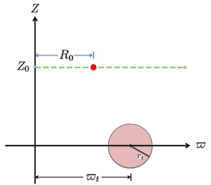
Referencing the illustration displayed in the left-hand panel of Figure 1, our goal is to determine the gravitational potential at any cylindrical-coordinate location <math>~(R_0, Z_0)</math> due to a uniform-density circular torus whose major radius is <math>~\varpi_t</math> and whose minor, cross-sectional radius is <math>~r_t</math>. | Referencing the illustration displayed in the left-hand panel of Figure 1, our goal is to determine the gravitational potential at any cylindrical-coordinate location <math>~(R_0, Z_0)</math> due to a uniform-density circular torus whose major radius is <math>~\varpi_t</math> and whose minor, cross-sectional radius is <math>~r_t</math>. | ||
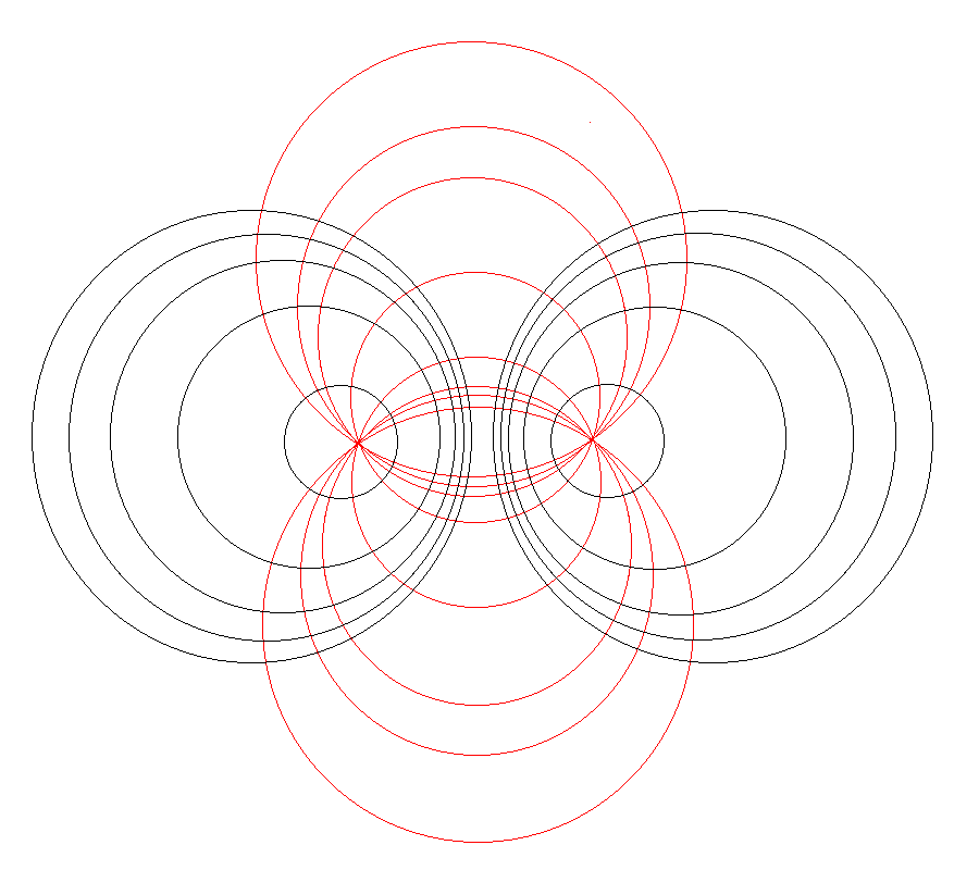
Here we explain how a toroidal coordinate system <math>~(\xi_1, \xi_2)</math> — as defined, for example, by MF53 and as illustrated schematically in the right-hand panel of Figure 1 — can be used to reduce the geometric complexity of this problem. | Here we explain how a toroidal coordinate system <math>~(\xi_1, \xi_2)</math> — as defined, for example, by MF53 and as illustrated schematically in the right-hand panel of Figure 1 — can be used to reduce the geometric complexity of this problem. Note that, in our illustration, each black circle identifies a <math>\xi_1 = </math> constant surface and each red circle identifies a <math>\xi_2 = </math> constant surface. Note, as well, that the overall length scale (not labeled in our schematic diagram) is set by the distance, <math>~a</math>, from the vertical symmetry axis to the origin of the toroidal coordinate system — the point (actually, the axisymmetric ring) at which all the red circles intersect one another. Here we will show how, when using an appropriately aligned toroidal coordinate system, the three-dimensional, weighted integral over the mass distribution can be reduced to the sum of a small number (1 - 4) of one-dimensional integrals over the "radial" <math>~(\xi_1)</math> coordinate. | ||
<table border="1" cellpadding="8" align="center"> | <table border="1" cellpadding="8" align="center"> | ||
| Line 39: | Line 39: | ||
</table> | </table> | ||
It should perhaps not be surprising to find that a toroidal coordinate system can be effectively used to quantitatively describe some properties — certainly the volume and possibly the gravitational potential — of circular tori because each <math>\xi_1 = </math> constant surface in a toroidal coordinate system (see the black circles in the right-hand panel of Figure 1) defines the surface of an axisymmetric, circular torus. In order to map from a cylindrical-coordinate representation of a circular torus (see the left-hand panel of Figure 1) to a toroidal-coordinate representation of that torus, at first glance it would seem reasonable to align the horizontal and vertical axes of the bipolar coordinate system (right-hand panel of Figure 1) with, respectively, the <math> | |||
It should perhaps not be surprising to find that a toroidal coordinate system can be effectively used to quantitatively describe some properties — certainly the volume and possibly the gravitational potential — of circular tori because each <math>\xi_1 = </math> constant surface in a toroidal coordinate system (see the black circles in the right-hand panel of Figure 1) defines the surface of an axisymmetric, circular torus. In order to map from a cylindrical-coordinate representation of a circular torus (see the left-hand panel of Figure 1) to a toroidal-coordinate representation of that torus, at first glance it would seem reasonable to establish the alignment depicted schematically in Figure 2. That is, align the horizontal and vertical axes of the bipolar coordinate system (right-hand panel of Figure 1) with, respectively, the <math>\varpi-</math>axis and the <math>Z-</math>axis of the cylindrical coordinate system, then scale the overall size of the bipolar coordinate system until one <math>\xi_1 = </math> constant surface perfectly aligns with the surface of the (pink) torus. This is the "special case" alignment that we have discussed in an accompanying chapter and is achieved by setting the scale-length, <math>~a</math>, of the toroidal-coordinate system to xxx, which means that the "radial" coordinate that aligns with the surface of the (pink) torus will have the value, yyyy. | |||
<table border="1" cellpadding="8" align="center" width="400px"> | |||
<tr> | |||
<th align="center" colspan="1"><font size="+1">Figure 2:</font> | |||
Schematic Illustration of Special Alignment</th> | |||
</tr> | |||
<tr> | |||
<td align="center"> | |||
[[File:MergedTorus01.png|400px|Merged image of (pink) circular torus and toroidal-coordinate system]] | |||
</td> | |||
</tr> | |||
<tr> | |||
<td align="left"> | |||
The pink circle represents the meridional cross-section through an axisymmetric, circular torus that lies in the equatorial plane of a cylindrical <math>~(\varpi, Z)</math>, coordinate system. The torus has a major axis of length, <math>~\varpi_t</math>, and a minor, cross-sectional radius of length, <math>~r_t</math>. The red circular dot identifies the cylindrical-coordinate location, <math>~(R_0, Z_0)</math>, at which the gravitational potential is to be evaluated. | |||
</td> | |||
</tr> | |||
</table> | |||
Revision as of 18:24, 11 November 2015
Toroidal-Coordinate Integration Limits
In support of our accompanying discussion of the gravitational potential of a uniform-density circular torus, here we explain in detail what limits of integration must be specified in order to accurately determine the volume — and, hence also the total mass — of such a torus using toroidal coordinates.

|
|---|
| | Tiled Menu | Tables of Content | Banner Video | Tohline Home Page | |
Preamble
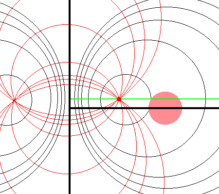
Referencing the illustration displayed in the left-hand panel of Figure 1, our goal is to determine the gravitational potential at any cylindrical-coordinate location <math>~(R_0, Z_0)</math> due to a uniform-density circular torus whose major radius is <math>~\varpi_t</math> and whose minor, cross-sectional radius is <math>~r_t</math>. Here we explain how a toroidal coordinate system <math>~(\xi_1, \xi_2)</math> — as defined, for example, by MF53 and as illustrated schematically in the right-hand panel of Figure 1 — can be used to reduce the geometric complexity of this problem. Note that, in our illustration, each black circle identifies a <math>\xi_1 = </math> constant surface and each red circle identifies a <math>\xi_2 = </math> constant surface. Note, as well, that the overall length scale (not labeled in our schematic diagram) is set by the distance, <math>~a</math>, from the vertical symmetry axis to the origin of the toroidal coordinate system — the point (actually, the axisymmetric ring) at which all the red circles intersect one another. Here we will show how, when using an appropriately aligned toroidal coordinate system, the three-dimensional, weighted integral over the mass distribution can be reduced to the sum of a small number (1 - 4) of one-dimensional integrals over the "radial" <math>~(\xi_1)</math> coordinate.
| Figure 1: Meridional slice through … | |
|---|---|
| (Pink) Circular Torus | Toroidal Coordinate System (schematic) (see also Wikipedia's Apollonian Circles) |
|
The pink circle represents the meridional cross-section through an axisymmetric, circular torus that lies in the equatorial plane of a cylindrical <math>~(\varpi, Z)</math>, coordinate system. The torus has a major axis of length, <math>~\varpi_t</math>, and a minor, cross-sectional radius of length, <math>~r_t</math>. The red circular dot identifies the cylindrical-coordinate location, <math>~(R_0, Z_0)</math>, at which the gravitational potential is to be evaluated. |
As is explained more fully in Wikipedia's discussion of toroidal coordinates, rotating this two-dimensional bipolar coordinate system about the vertical axis produces a three-dimensional toroidal coordinate system. Black circles centered on the horizontal axis become circular tori — each identifying an axisymmetric, <math>\xi_1 =</math> constant surface; whereas, red circles centered on the vertical axis become spheres — each identifying an axisymmetric, <math>\xi_2 =</math> constant surface. |
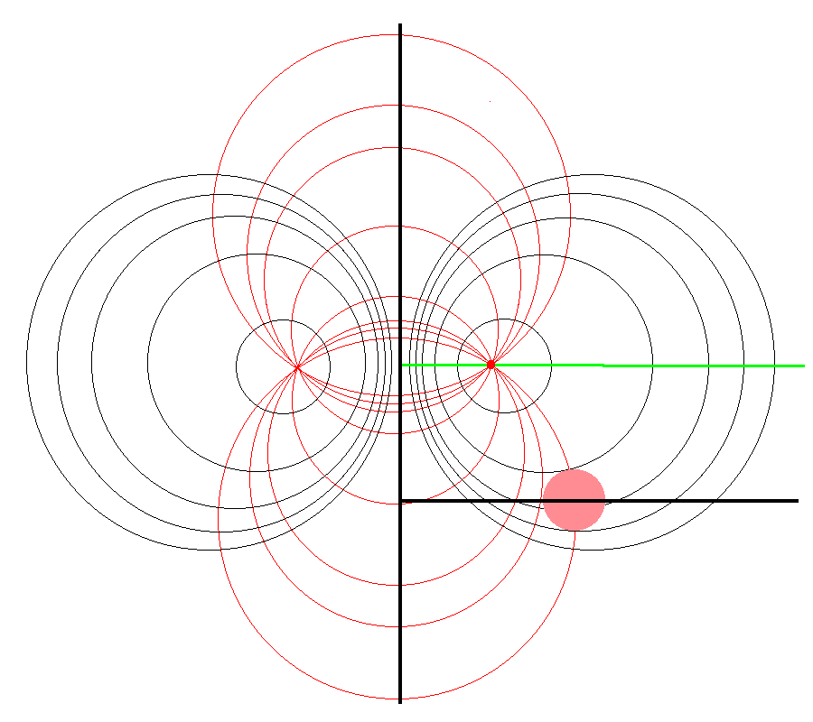
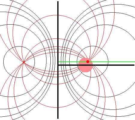
It should perhaps not be surprising to find that a toroidal coordinate system can be effectively used to quantitatively describe some properties — certainly the volume and possibly the gravitational potential — of circular tori because each <math>\xi_1 = </math> constant surface in a toroidal coordinate system (see the black circles in the right-hand panel of Figure 1) defines the surface of an axisymmetric, circular torus. In order to map from a cylindrical-coordinate representation of a circular torus (see the left-hand panel of Figure 1) to a toroidal-coordinate representation of that torus, at first glance it would seem reasonable to establish the alignment depicted schematically in Figure 2. That is, align the horizontal and vertical axes of the bipolar coordinate system (right-hand panel of Figure 1) with, respectively, the <math>\varpi-</math>axis and the <math>Z-</math>axis of the cylindrical coordinate system, then scale the overall size of the bipolar coordinate system until one <math>\xi_1 = </math> constant surface perfectly aligns with the surface of the (pink) torus. This is the "special case" alignment that we have discussed in an accompanying chapter and is achieved by setting the scale-length, <math>~a</math>, of the toroidal-coordinate system to xxx, which means that the "radial" coordinate that aligns with the surface of the (pink) torus will have the value, yyyy.
| Figure 2: Schematic Illustration of Special Alignment |
|---|
|
The pink circle represents the meridional cross-section through an axisymmetric, circular torus that lies in the equatorial plane of a cylindrical <math>~(\varpi, Z)</math>, coordinate system. The torus has a major axis of length, <math>~\varpi_t</math>, and a minor, cross-sectional radius of length, <math>~r_t</math>. The red circular dot identifies the cylindrical-coordinate location, <math>~(R_0, Z_0)</math>, at which the gravitational potential is to be evaluated. |
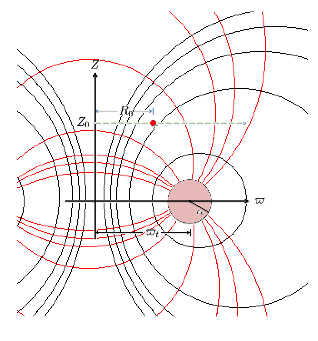
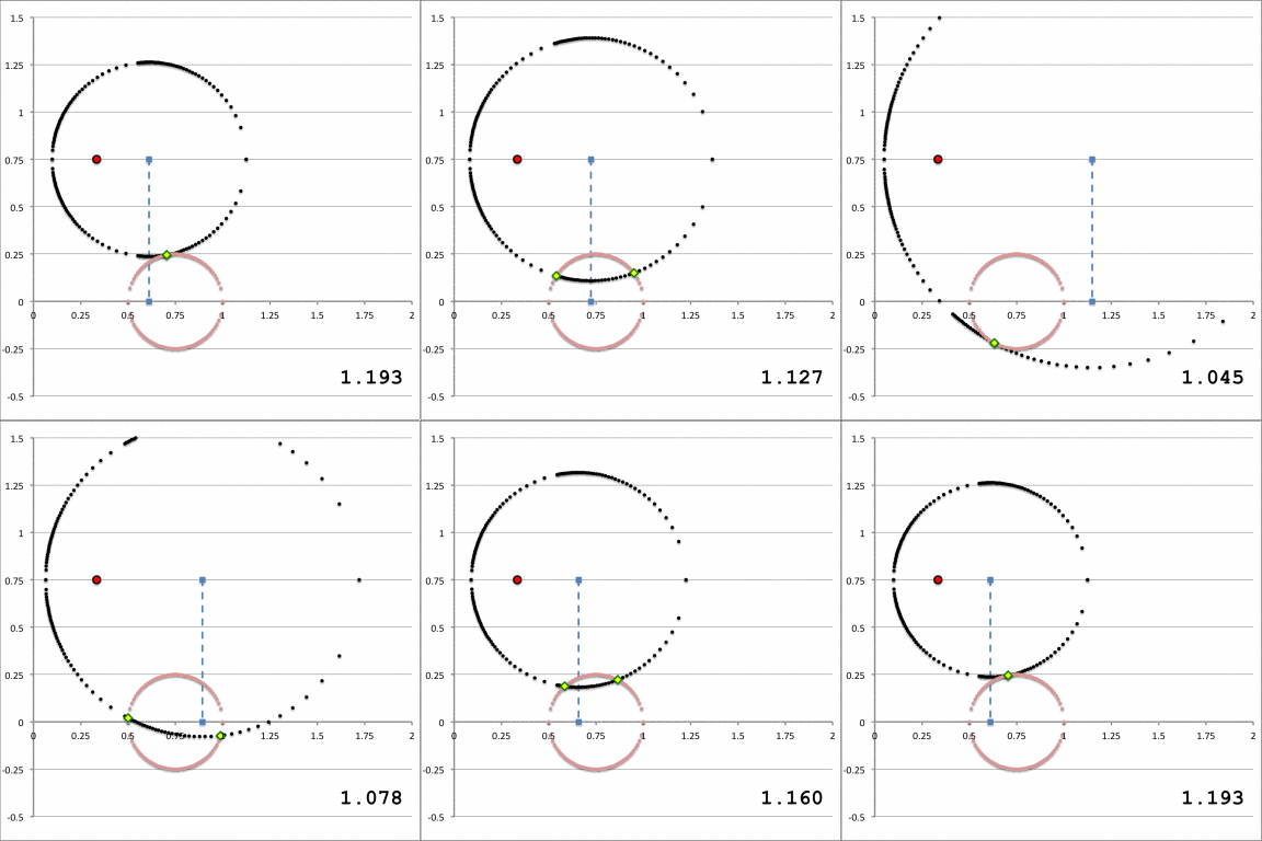
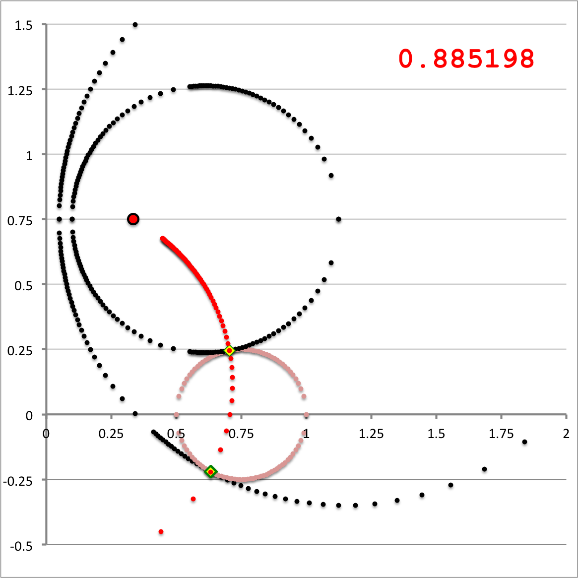
| Quantitative Illustration of Employed Toroidal Coordinate System | ||
|---|---|---|
| Schematic Zones | ||
|---|---|---|
| Zone I <math>~Z_0 > r_t</math>for any <math>~a</math> | Zone II <math>~r_t > Z_0 > 0</math>and<math>~a < \varpi_t - \sqrt{r_t^2 - Z_0^2}</math> | Zone III <math>~r_t > Z_0 > 0</math>and<math>~\varpi_t - \sqrt{r_t^2 - Z_0^2} < a < \varpi_t + \sqrt{r_t^2 - Z_0^2}</math> |
|
|
See Also

|
|---|
|
© 2014 - 2021 by Joel E. Tohline |
