User:Tohline/Appendix/CGH/ParallelAperturesHolograms
CGH: Relevance to Holograms
This chapter is intended primarily to replicate §I.C from the online class notes — see also an updated Table of Contents — that I developed in conjunction with a course that I taught in 1999 on the topic of Computer Generated Holography (CGH) for a subset of LSU physics majors who were interested in computational science.

|
|---|
| | Tiled Menu | Tables of Content | Banner Video | Tohline Home Page | |
Basic Concept
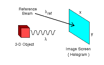
Okay, so what do §§I.A and I.B have to do with the numerical construction of a hologram? Well, this is best explained by borrowing an illustration from the Nishikawa et al. (1997) paper (redrawn here as Figure I.2), and comparing it with Figure I.1 from our §I.A.
| Figure I.2 |
|---|
 |
In general a hologram is made by combining light of wavelength, <math>~\lambda</math>, that is coming from the surface of a 3-dimensional object with coherent light from a reference beam of wavelength <math>~\lambda_\mathrm{ref}</math>. The interference pattern that is created on the "image screen" via the combination of these two separate sources of light is recorded as the hologram — usually in the form of an exposed piece of photographic film. Let's consider the behavior of these two sources of light, separately.
Light from the Object
The discussions in §§I.A and I.B illustrate how light that originates from an extended object (aperture) illuminates various points along the image screen. For example, from the perspective of the image screen, the front vertical edge of the red cube shown above in Figure I.2 looks like a vertical, one-dimensional "slit" aperture of width "w", as illustrated in Figure I.1 from our §I.A. Hence, the complex amplitude of light that is striking various points "y" along any vertical column of the image screen (hologram) due solely to the light coming from this edge of the cube is given by the expression derived in §I.A, namely,
|
<math>~A(y)</math> |
<math>~\approx</math> |
<math>~ [A_0~a_0~w] \mathrm{sinc}(\beta) \, , </math> |
where,
|
<math>~\beta</math> |
<math>~ \equiv </math> |
<math>~ \frac{\pi y w}{\lambda L} \, , </math> |
|
<math>~L</math> |
<math>~ \equiv </math> |
<math>~ [Z^2 + y^2]^{1 / 2} \, , </math> |
Z is the shortest distance measured between the front vertical edge of the cube and the selected column of the image screen, and for purposes of illustration, we have set to zero the offset phase angle, <math>~\vartheta_1</math>, that appears in our previously derived analytic expression for the amplitude.
However, as depicted in Figure I.2, the image screen is not being illuminated by just one vertical edge of the cube but, instead, by one entire two-dimensional face of the cube (the side of the cube that is facing to the right and is therefore not visible in the figure). From the perspective of the image screen (hologram), the surface of the cube looks like a two-dimensional aperture of width "w" and height "w." Therefore, the more complete expression for the complex amplitude of light striking the image screen is,
|
<math>~A(x, y)</math> |
<math>~\approx</math> |
<math>~ [A_0~a_0~w^2] \mathrm{sinc}(\alpha)~\mathrm{sinc}(\beta) \, , </math> |
where,
|
<math>~\alpha</math> |
<math>~ \equiv </math> |
<math>~ \frac{\pi x w}{\lambda L} \, , </math> |
|
<math>~\beta</math> |
<math>~ \equiv </math> |
<math>~ \frac{\pi y w}{\lambda L} \, , </math> |
|
<math>~L</math> |
<math>~ \equiv </math> |
<math>~ [Z^2 + y^2 + x^2]^{1 / 2} \, , </math> |
as derived in our accompanying discussion of two-dimensional apertures that are parallel to the image screen. (Again, as in our separate discussion, for the sake of illustration we have set the two offset phase angles, <math>~\Theta_1 = \vartheta_1 = 0</math>.)
See Also
- Updated Table of Contents
- Born, M. and Wolf, E. (1980) Principles of Optics, 3rd Edition. New York: Pergamon Press. [See especially their §§8.5 and 8.10.] A link to the 6th edition of this book can be found here.
- Nishikawa, O., Okada, T., Yoshikawa, H., Sato, K. and Honda, T. (February 1997), High-Speed Holographic-Stereogram Calculation Method Using 2D FFT, Proc. SPIE 3010, Diffractive and Holographic Device Technologies and Applications IV, (15 May 1997); paper #3010-10.

|
|---|
|
© 2014 - 2021 by Joel E. Tohline |