Difference between revisions of "User:Tohline/Appendix/Ramblings/RiemannMeetsOculus"
| Line 280: | Line 280: | ||
<font color="darkgreen"><b>b41c385Rot02.dae</b></font> (rotating frame): | <font color="darkgreen"><b>b41c385Rot02.dae</b></font> (rotating frame): | ||
<br />First, we inserted just the "equal" sign and did ''not'' mix it in with the animated "MidPlane Frame." We were able to view this model inside the Oculus Rift S environment, as well as with the Mac's Preview app. | <br />First, we inserted just the "equal" sign and did ''not'' mix it in with the animated "MidPlane Frame." We were able to view this model inside the Oculus Rift S environment, as well as with the Mac's Preview app. | ||
</li> | |||
<li> | |||
<font color="darkgreen"><b>b41c385Rot05.dae</b></font> (rotating frame): | |||
<br />This appears to be the best way to handle the rotating frame when the inertial-frame spin of the ellipsoid is counter-clockwise — hence, the rotating "Frame" spin should be clockwise. | |||
<ol> | |||
<li>The "MidPlane" <animation> specification should be entirely in terms of positive angles; for example, | |||
<pre> | |||
<!-- This sets the spin rate of the "MidPlane" Frame of reference --> | |||
<source id="Frame_rotation_euler_Z-output"> | |||
<float_array id="Frame_rotation_euler_Z-output-array" count="31"> | |||
3.0 | |||
63.0 | |||
123.0 | |||
183.0 | |||
... | |||
1683.0 | |||
1743.0 | |||
1803.0 | |||
</float_array> | |||
<technique_common> | |||
<accessor source="#Frame_rotation_euler_Z-output-array" count="31" stride="1"> | |||
<param name="ANGLE" type="float"/> | |||
</accessor> | |||
</technique_common> | |||
</source> | |||
</pre> | |||
</li> | |||
<li> | |||
The relevant <channel> specification should be target="Inertial/rotationZ.ANGLE". | |||
</li> | |||
<li> | |||
The overarching parent <node id="Inertial" …> should flip ''every'' child node that is part of the laboratory infrastructure, then begin the clockwise rotation by specifying the initial "rotationZ" = 3.0, to match the initial spin angle specified in the <animation>. In this example, we have … | |||
<pre> | |||
<node id="Inertial" name="instance_inertial"> <!-- Start Inertial Grouping of Objects --> | |||
<translate>0.0 0.0 0.0</translate> | |||
<rotate sid="rotationX">1.0 0.0 0.0 180.0</rotate> | |||
<rotate sid="rotationY">0.0 1.0 0.0 0.0</rotate> | |||
<rotate sid="rotationZ">0.0 0.0 1.0 3.0</rotate> | |||
<scale sid="scale">1.25 1.25 1.25</scale> | |||
<node id="Zup_Pointer" name="instance_zupPointer"> | |||
<translate>0.0 0.0 -5.0</translate> | |||
<rotate sid="rotationX">1 0 0 0.0</rotate> | |||
<rotate sid="rotationY">0 1 0 0.0</rotate> | |||
<rotate sid="rotationZ">0 0 1 0.0</rotate> | |||
<scale sid="scale">0.125 0.5 1.5</scale> | |||
<instance_node url="#ZupPointer" /> | |||
</node> | |||
<!-- instance: MidPlane Frame (MidPlane flips with rotationX = 180 for clockwise spin)--> | |||
<node id="MidPlane" name="instance_MidPlane"> | |||
<translate>0.0 0.0 0.0</translate> | |||
<rotate sid="rotationX">1.0 0.0 0.0 0.0</rotate> | |||
<rotate sid="rotationY">0.0 1.0 0.0 0.0</rotate> | |||
<rotate sid="rotationZ">0.0 0.0 1.0 0.0</rotate> | |||
<scale sid="scale">1.25 1.25 1.25</scale> | |||
<instance_node url="#EqPlane" /> | |||
</node> | |||
<!-- BEGIN LABELING HERE --> | |||
<node name="Labels"> | |||
<translate>7.5 -2.0 -5.0</translate> | |||
<rotate sid="rotationX">1 0 0 0</rotate> | |||
<rotate sid="rotationY">0 1 0 0</rotate> | |||
<rotate sid="rotationZ">0 0 1 180</rotate> | |||
<scale sid="scale">0.1 0.1 0.1</scale> | |||
<!-- Equals sign #1 --> | |||
<node name="Equals1"> | |||
<translate>0.0 15.0 1.0</translate> | |||
<rotate sid="rotationX">1 0 0 0</rotate> | |||
<rotate sid="rotationY">0 1 0 0</rotate> | |||
<rotate sid="rotationZ">0 0 1 0</rotate> | |||
<scale sid="scale">1.0 1.0 1.0</scale> | |||
<node id="IDd51" name="instance_51"> | |||
<matrix>0.25 0 0 0.0 0 1 0 0.0 0 0 1 2.4 0 0 0 1.0</matrix> | |||
<instance_node url="#LettersID3" /> | |||
</node> | |||
<node id="IDd52" name="instance_52"> | |||
<matrix>0.25 0 0 0.0 0 1 0 1.1 0 0 1 2.4 0 0 0 1.0</matrix> | |||
<instance_node url="#LettersID3" /> | |||
</node> | |||
<node id="IDd53" name="instance_53"> | |||
<matrix>0.25 0 0 0.0 0 1 0 2.2 0 0 1 2.4 0 0 0 1.0</matrix> | |||
<instance_node url="#LettersID3" /> | |||
</node> | |||
<node id="IDd55" name="instance_55"> | |||
<matrix>0.25 0 0 0.0 0 1 0 0.0 0 0 1 4.2 0 0 0 1.0</matrix> | |||
<instance_node url="#LettersID3" /> | |||
</node> | |||
<node id="IDd56" name="instance_56"> | |||
<matrix>0.25 0 0 0.0 0 1 0 1.1 0 0 1 4.2 0 0 0 1.0</matrix> | |||
<instance_node url="#LettersID3" /> | |||
</node> | |||
<node id="IDd57" name="instance_57"> | |||
<matrix>0.25 0 0 0.0 0 1 0 2.2 0 0 1 4.2 0 0 0 1.0</matrix> | |||
<instance_node url="#LettersID3" /> | |||
</node> | |||
</node> | |||
</node> | |||
<!-- END LABELING HERE --> | |||
</node> <!-- End Inertial Grouping of Objects --> | |||
</pre> | |||
</li> | |||
</ol> | |||
</li> | </li> | ||
Revision as of 21:19, 7 May 2020
Rebuild Riemann S-Type Ellipsoid Inside Oculus Rift S Environment

|
|---|
| | Tiled Menu | Tables of Content | Banner Video | Tohline Home Page | |
Preamble
In an accompanying discussion, we have illustrated how an animated, interactive 3D scene can be largely defined via the xml-formatted language named COLLADA. In the last major subsection of that discussion, we have outlined the steps that can be followed to specifically generate any of a variety of Riemann S-Type ellipsoids. These steps were identified within the context of our effort to construct 3D VR/AR models that could be faithfully rendered using the Mac's Preview app.
In a separate but closely connected discussion, we have demonstrated that most of our COLLADA-based models can be imported into the 3D virtual-reality environment of the Oculus Rift S. Toward the end of this separate discussion, we provide the full COLLADA code — in a plain text format — along with a summary description of a model that has been assigned the name, FullLast45X.dae.
Intially, we discovered that most of the Riemann S-Type ellipsoids that we developed while relying on the Mac's Preview app did not display properly within the Oculus Rift S environment. What we propose to do, here, is methodically re-construct a variety of our earlier models that were viewable in the "Preview" app in such a way that they are all viewable with the Oculus Rift S. We begin with this "… 45X" model — renaming it, RiemannBuild00.dae. Step by step we will insert components of one of our previously constructed COLLADA-based models of an S-Type Riemann ellipsoid into a <visual_scene> that can be properly executed within the Oculus Rift S.
Assemble Components
-
RiemannBuild00.dae:
- This model, with <up_axis>Z_UP></up_axis>, contains a set of purple cubes that lie in the Y0-Z0 plane, and along the inertial frame's X0 axis from -5.0 inches to +5.0 inches; the last purple "cube" (at X0 = +5) is actually a rectangular box whose longest axis is parallel to the Z0 axis.
Mac Preview of RiemannBuild00.dae 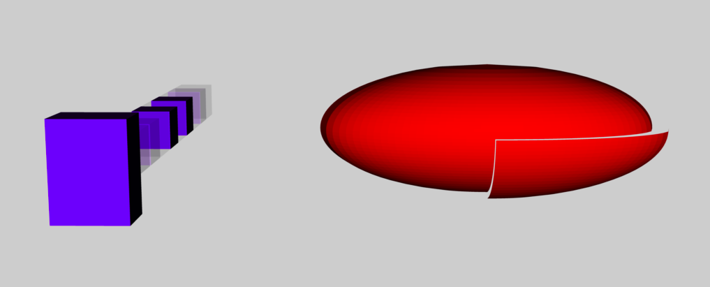
- The scene also includes a red ellipsoid with axis ratios b/a = 0.41 and c/a = 0.385. The "EntireEllipsoid" has been scaled such that its longest ( c ) axis has a length of 4 inches; and it has been translated in the Y0-Z0 plane to a location along the Y0 axis where the center of the ellipsoid is 8.0 inches from the origin of the inertial coordinate system. The ellipsoid's "First" quadrant <node> was, in addition, scaled by (1.1, 1.1, 1.1) in order for it to stick out a bit from the other quadrants to help the viewer decipher its rotational behavior.
<node id="EntireEllipsoid" name="OculusRift_EFE"> <translate>0.0 8.0 0.0</translate> <rotate sid="rotationY">0.0 1.0 0.0 90.0</rotate> <rotate sid="rotationZ">0.0 0.0 1.0 90.0</rotate> <rotate sid="rotationX">1.0 0.0 0.0 90.0</rotate> <scale sid="scale">4.0 4.0 4.0</scale> <node id="First" name="First_instance_EFE"> <translate>0.0 0.0 0.0</translate> <rotate sid="rotationX">1.0 0.0 0.0 0.0</rotate> <rotate sid="rotationY">0.0 1.0 0.0 0.0</rotate> <rotate sid="rotationZ">0.0 0.0 1.0 0.0</rotate> <scale sid="scale">1.1 1.1 1.1</scale> <instance_node url="#ID3_EFE" /> </node> ... - The default orientation of the "EntireEllipsoid" is <math>~(a, b, c) \Leftrightarrow ~ (X_0, Y_0, Z_0)</math>. But for this model, before the animation starts, the "EntireEllipsoid" is reoriented by turning it 90° in Y, then 90° in Z, then 90° in X; as displayed in the above image, this resulted in an alignment of <math>~(a, b, c) \Leftrightarrow ~ (Y_0, X_0, -Z_0)</math>.
-
The set of <animation> instructions includes a specification that, (1) TIME start at 0.0 seconds and end (one animation loop) at 10.0 seconds; (2) over this time interval, the rotation ANGLE should start at 90° and end at 270° [in COLLADA, it is understood that the ANGLE will vary linearly with TIME, unless explicitly specified otherwise]; and (3) via the <channel/target> instruction, the rotation should be about the longest (rotationX) axis of the ellipsoid.
      <float_array id="First_rotation_euler_Y-input-array" count="    2">
    0.0000
   10.0000
      </float_array>
                ...
      <float_array id="First_rotation_euler_Y-output-array" count="    2">
    90.0
   270.0
      </float_array>
                ...
    <channel source="#First_rotation_euler_Y-sampler" target="EntireEllipsoid/rotationX.ANGLE"/>
- This model, with <up_axis>Z_UP></up_axis>, contains a set of purple cubes that lie in the Y0-Z0 plane, and along the inertial frame's X0 axis from -5.0 inches to +5.0 inches; the last purple "cube" (at X0 = +5) is actually a rectangular box whose longest axis is parallel to the Z0 axis.
-
RiemannBuild02.dae:
-
Got rid of all of the <visual_scene><nodes> that had been used to create the line of purple "cubes"; set the "EntireEllipsoid" <translate> coordinate to zero in all three dimensions so that the center of the red ellipsoid coincided with the origin of the principal frame of reference; set to zero the values of all three <rotate> ANGLEs for the "EntireEllipsoid" so that the red ellipsoid was initially positioned in its default orientation, that is, <math>~(a, b, c) ~\Leftrightarrow ~(X_0, Y_0, Z_0)</math>;
            <node id="EntireEllipsoid" name="OculusRift_EFE">
             <translate>0.0 0.0 0.0</translate>
             <rotate sid="rotationX">1.0 0.0 0.0  0.0</rotate>
             <rotate sid="rotationY">0.0 1.0 0.0  0.0</rotate>
             <rotate sid="rotationZ">0.0 0.0 1.0  0.0</rotate>
             <scale sid="scale">5.0 5.0 5.0</scale>
                <node id="First" name="First_instance_EFE">
                  <translate>0.0 0.0 0.0</translate>
                  <rotate sid="rotationX">1.0 0.0 0.0  0.0</rotate>
                  <rotate sid="rotationY">0.0 1.0 0.0  0.0</rotate>
                  <rotate sid="rotationZ">0.0 0.0 1.0  0.0</rotate>
                  <scale sid="scale">1.1 1.1 1.1</scale>
                  <instance_node url="#ID3_EFE" />
                </node>
                ...
and set the <animation> parameters such that, over a 10 second interval of time, using the <channel … target="EntireEllipsoid/rotationZ.ANGLE"/> directive the ellipsoid was instructed to spin about the shortest ( c ) axis, from 0° to 180°.
      <float_array id="First_rotation_euler_Z-input-array" count="    2">
    0.0000
   10.0000
      </float_array>
                ...
      <float_array id="First_rotation_euler_Z-output-array" count="    2">
    0.0
   180.0
      </float_array>
                ...
    <channel source="#First_rotation_euler_Z-sampler" target="EntireEllipsoid/rotationZ.ANGLE"/>
RESULT: Using the Mac's Preview app to view this modified COLLADA file, the (now) isolated red ellipsoid did spin, as desired, through 180° about the ellipsoid's shortest axis. But when imported into the Oculus Rift S environment, the isolated red ellipsoid was spinning about the ellipsoid's longest axis. I don't understand why!
-
Got rid of all of the <visual_scene><nodes> that had been used to create the line of purple "cubes"; set the "EntireEllipsoid" <translate> coordinate to zero in all three dimensions so that the center of the red ellipsoid coincided with the origin of the principal frame of reference; set to zero the values of all three <rotate> ANGLEs for the "EntireEllipsoid" so that the red ellipsoid was initially positioned in its default orientation, that is, <math>~(a, b, c) ~\Leftrightarrow ~(X_0, Y_0, Z_0)</math>;
-
RiemannBuild03.dae:
Here, we implemented only two changes to the COLLADA code: (1) We modified the "EntireEllipsoid" <node>'s "rotationZ" instruction to specify that, prior to implementing the rotation, the ellipsoid should be turned 1° [instead of zero degrees] about the shortest ( c ) axis;
            <node id="EntireEllipsoid" name="OculusRift_EFE">
             <translate>0.0 0.0 0.0</translate>
             <rotate sid="rotationX">1.0 0.0 0.0  0.0</rotate>
             <rotate sid="rotationY">0.0 1.0 0.0  0.0</rotate>
             <rotate sid="rotationZ">0.0 0.0 1.0  1.0</rotate>
             <scale sid="scale">5.0 5.0 5.0</scale>
                ...
and (2) inside the set of <animation> instructions, we specified that the time-dependent ANGLE should have a starting (TIME = 0.0) value of 1° and an ending (TIME = 10.0) value of 180°.
      <float_array id="First_rotation_euler_Z-output-array" count="    2">
    1.0
   180.0
      </float_array>
                ...
RESULT: The desired behavior — that is, spinning about the shortest ( c ) axis from 1° to 180° — was observed in both the Mac's Preview app and in the Oculus Rift S environment. But I don't actually understand why the Oculus import resulted in two quite different spinning motions, given that the starting ANGLE was only changed from 0° to 1°. -
RiemannBuild05.dae:
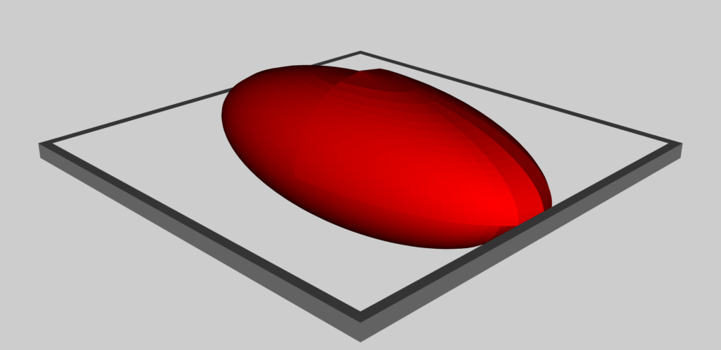
Pulling from the file named, b41c385_DI.dae, we added a "MidPlane Frame" to the visual_scene. This worked in the Oculus Rift S environment as well as in the Mac's Preview app (see image immediately below).
| Mac Preview of … | ||
|
RiemannBuild05.dae |
RiemannBuild06.dae |
RiemannBuild09D.dae |
-
RiemannBuild06.dae:
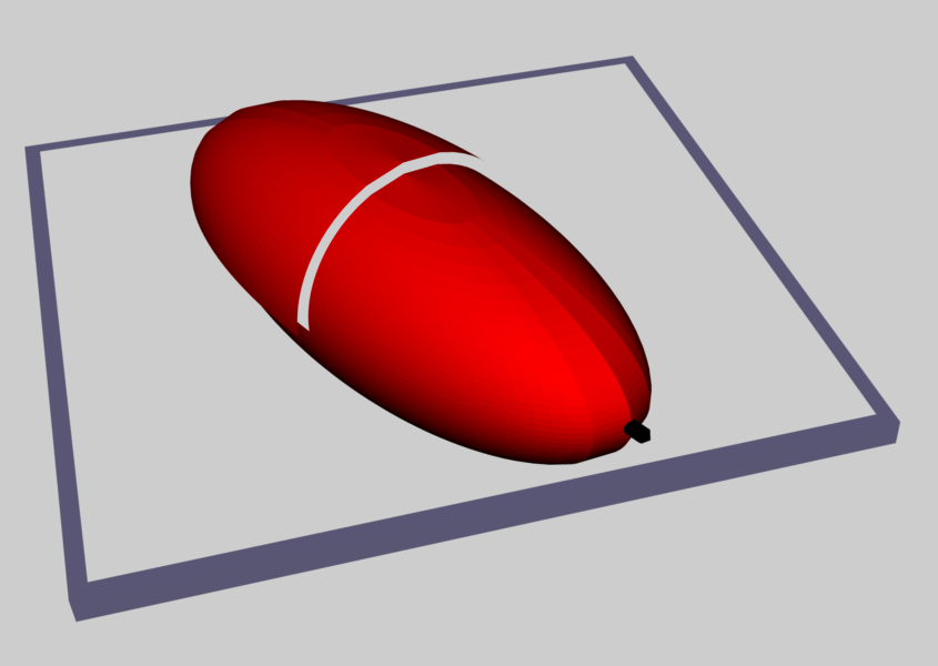
Pulling from the file named, b41c385_DI.dae, we added a "Black Cylindrical Pointer" to the visual_scene. This worked in the Oculus Rift S environment as well as in the Mac's Preview app. -
RiemannBuild09D.dae:
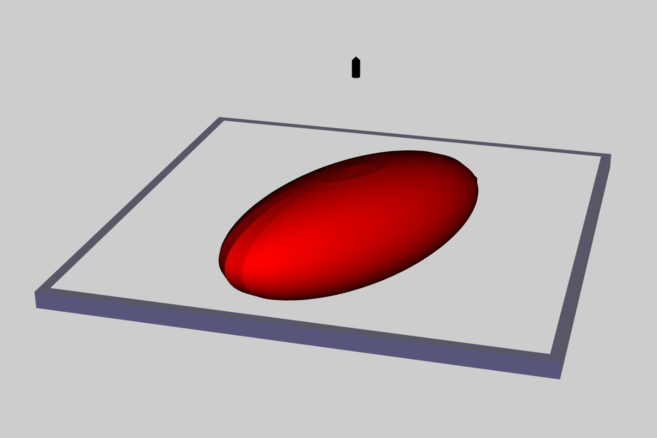
After much trial and error, we have successfully introduced two separate animation instructions. In addition to instructing the visual scene to spin the red ellipsoid about its "c" axis at a specific rate, we can now instruct the visual scene to spin the "MidPlane Frame" about the same axis, but in the opposite direction (at any specified rate), in order to mimic a rotating frame of reference. As the above image from the Mac Preview app shows, we have also added a second "Black Cylindrical Pointer", orienting it in the positive Z0 direction; and we have removed the special scaling of the "First" quadrant of the ellipsoid that had been introduced in earlier models to break the geometric symmetry of the object, thereby helping us to keep track of changes in the model's spin directions and rates. - RiemannBuild09G.dae: Fixed the way the second "Black Cylindrical Pointer" is handled.
|
-
Mac Preview of
RiemannLagrange12L.dae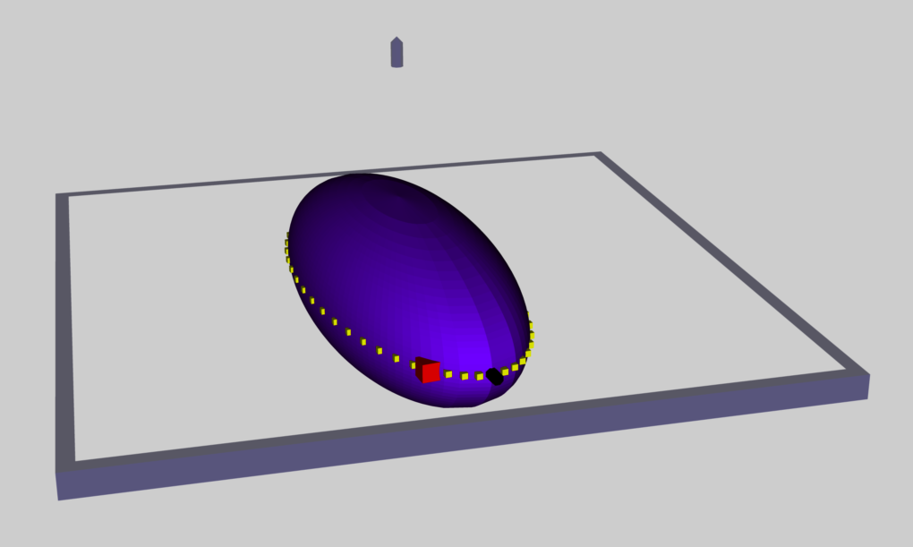
RiemannBuild10C.dae:
Hold the red ellipsoid completely still at ANGLE = 0° while the MidPlane Frame spins briskly clockwise. In addition to typing in the floating-point value, 0.0, a dozen times to correlate with the twelve different specified increments of TIME, we also changed the initial value of "rotationZ" from "4.0" to "0.0" inside the "EntireEllipsoid" <node>.
RESULT: Seems to work in both visualization venues. -
RiemannLagrange11B.dae:
Insert 51 small yellow (cube) "Markers" in the equatorial plane and on the surface of the red ellipsoid to identify the trajectory of a Lagrangian fluid element. -
RiemannLagrange12L.dae (rotating frame):
Include one solitary Lagrangian fluid element (red marker that is a bit larger than the previously inserted small yellow cubes), showing its "retrograde" motion in the equatorial plane and on the surface of the — now opaque, purple — ellipsoid (see Mac Preview image shown here, on the right). In this model, the displayed time-dependent behavior — the spinning "MidPlane Frame" and the red Lagrangian fluid marker — is quantitatively correct for an S-Type Riemann ellipsoid that has the specific principal axis ratios — that is, b/a = 0.41 and c/a = 0.385 — of the displayed purple ellipsoid, and that is being viewed from a rotating frame of reference in which the ellipsoid is stationary.
There is still a funny issure related to the "Zup Pointer". Over time, it gains a bit of tilt. -
RiemannLagrange12M.dae (inertial frame):
In an effort to diagnose/deal with the "Zup Pointer" issue (see RiemannLagrange12L.dae), this model attempts to move to the inertial frame of reference. The Zup Pointer appears to remain stationary, and pointed precisely the desired direction. This model (or maybe it was model …14P) does not import properly into the Oculus Rift. I can see the model, but Oculus outlines the scene in red, and displays red exclamation marks, to indicate that it does not like what the conversion routine has generated. -
RiemannLagrange14Q.dae (inertial frame):
My guess is that the Oculus Rift (or the KG's conversion routine) has a problem dealing with the coordinate singularity along the Z-axis — that is, all longitudes lines reach the pole of the spherical coordinate system at the same (or at an undetermined value of the) azimuthal angle. So, instead of using the geometric object [the "Cylindrical Pointer"] that was created to highlight the negative X-axis of the ellipsoid, here we are identifying the Z_0 axis by stretching the "Cube" geometric object into a "long" thin solid rectangle and placing it along the Z_0 axis. This new "Zup Pointer" seems to work in both visualization venues.
S-Type Ellipsoid b41c385
Now, let's add the wall clock and alpha-numeric identification of the model's parameters. To start with, we have made a copy of "RiemannLagrange12L.dae" and renamed it, b41c385Rot00.dae
-
b41c385Rot02.dae (rotating frame):
First, we inserted just the "equal" sign and did not mix it in with the animated "MidPlane Frame." We were able to view this model inside the Oculus Rift S environment, as well as with the Mac's Preview app. -
b41c385Rot05.dae (rotating frame):
This appears to be the best way to handle the rotating frame when the inertial-frame spin of the ellipsoid is counter-clockwise — hence, the rotating "Frame" spin should be clockwise.- The "MidPlane" <animation> specification should be entirely in terms of positive angles; for example,
<!-- This sets the spin rate of the "MidPlane" Frame of reference --> <source id="Frame_rotation_euler_Z-output"> <float_array id="Frame_rotation_euler_Z-output-array" count="31"> 3.0 63.0 123.0 183.0 ... 1683.0 1743.0 1803.0 </float_array> <technique_common> <accessor source="#Frame_rotation_euler_Z-output-array" count="31" stride="1"> <param name="ANGLE" type="float"/> </accessor> </technique_common> </source> - The relevant <channel> specification should be target="Inertial/rotationZ.ANGLE".
-
The overarching parent <node id="Inertial" …> should flip every child node that is part of the laboratory infrastructure, then begin the clockwise rotation by specifying the initial "rotationZ" = 3.0, to match the initial spin angle specified in the <animation>. In this example, we have …
          <node id="Inertial" name="instance_inertial">  <!-- Start Inertial Grouping of Objects -->
            <translate>0.0 0.0 0.0</translate>
            <rotate sid="rotationX">1.0 0.0 0.0  180.0</rotate>
            <rotate sid="rotationY">0.0 1.0 0.0  0.0</rotate>
            <rotate sid="rotationZ">0.0 0.0 1.0  3.0</rotate>
            <scale sid="scale">1.25 1.25 1.25</scale>
            <node id="Zup_Pointer" name="instance_zupPointer">
              <translate>0.0 0.0 -5.0</translate>
                <rotate sid="rotationX">1 0 0  0.0</rotate>
                <rotate sid="rotationY">0 1 0  0.0</rotate>
                <rotate sid="rotationZ">0 0 1  0.0</rotate>
              <scale sid="scale">0.125 0.5 1.5</scale>
              <instance_node url="#ZupPointer" />
            </node>
<!-- instance:  MidPlane Frame (MidPlane flips with rotationX = 180 for clockwise spin)-->
            <node id="MidPlane" name="instance_MidPlane">
              <translate>0.0 0.0 0.0</translate>
                  <rotate sid="rotationX">1.0 0.0 0.0  0.0</rotate>
                  <rotate sid="rotationY">0.0 1.0 0.0  0.0</rotate>
                  <rotate sid="rotationZ">0.0 0.0 1.0  0.0</rotate>
              <scale sid="scale">1.25 1.25 1.25</scale>
              <instance_node url="#EqPlane" />
            </node>
<!-- BEGIN LABELING HERE -->
          <node name="Labels">
          <translate>7.5 -2.0 -5.0</translate>
          <rotate sid="rotationX">1 0 0 0</rotate>
          <rotate sid="rotationY">0 1 0 0</rotate>
          <rotate sid="rotationZ">0 0 1 180</rotate>
          <scale sid="scale">0.1 0.1 0.1</scale>
<!--  Equals sign #1  -->
            <node name="Equals1">
            <translate>0.0 15.0 1.0</translate>
            <rotate sid="rotationX">1 0 0 0</rotate>
            <rotate sid="rotationY">0 1 0 0</rotate>
            <rotate sid="rotationZ">0 0 1 0</rotate>
            <scale sid="scale">1.0 1.0 1.0</scale>
                <node id="IDd51" name="instance_51">
                    <matrix>0.25  0 0 0.0   0 1  0 0.0  0 0 1 2.4  0 0 0 1.0</matrix>
                    <instance_node url="#LettersID3" />
                </node>
                <node id="IDd52" name="instance_52">
                    <matrix>0.25  0 0 0.0   0 1  0 1.1  0 0 1 2.4  0 0 0 1.0</matrix>
                    <instance_node url="#LettersID3" />
                </node>
                <node id="IDd53" name="instance_53">
                    <matrix>0.25  0 0 0.0   0 1  0 2.2  0 0 1 2.4  0 0 0 1.0</matrix>
                    <instance_node url="#LettersID3" />
                </node>
                <node id="IDd55" name="instance_55">
                    <matrix>0.25  0 0 0.0   0 1  0 0.0  0 0 1 4.2  0 0 0 1.0</matrix>
                    <instance_node url="#LettersID3" />
                </node>
                <node id="IDd56" name="instance_56">
                    <matrix>0.25  0 0 0.0   0 1  0 1.1  0 0 1 4.2  0 0 0 1.0</matrix>
                    <instance_node url="#LettersID3" />
                </node>
                <node id="IDd57" name="instance_57">
                    <matrix>0.25  0 0 0.0   0 1  0 2.2  0 0 1 4.2  0 0 0 1.0</matrix>
                    <instance_node url="#LettersID3" />
                </node>
            </node>
          </node>
<!-- END LABELING HERE -->
          </node> <!-- End Inertial Grouping of Objects -->
- The "MidPlane" <animation> specification should be entirely in terms of positive angles; for example,
See Also

|
|---|
|
© 2014 - 2021 by Joel E. Tohline |
