Difference between revisions of "User:Tohline/Appendix/CGH/Overview"
| (4 intermediate revisions by the same user not shown) | |||
| Line 1: | Line 1: | ||
<!-- __FORCETOC__ will force the creation of a Table of Contents --> | <!-- __FORCETOC__ will force the creation of a Table of Contents --> | ||
<!-- __NOTOC__ will force TOC off --> | <!-- __NOTOC__ will force TOC off --> | ||
=CGH: | =CGH: Design Overview= | ||
{{LSU_HBook_header}} | {{LSU_HBook_header}} | ||
Here we outline a research project that builds upon the extraordinary work of [http://www.phys.lsu.edu/~tohline/phys4412/howto/DynamicHolographic3dImageProjection.pdf Huebschman, Manjuluri, & Garner (2003)] titled, ''Dynamic holographic 3-D image projection''. | |||
<table border="1" cellpadding="8" align="center"> | |||
<tr> | |||
<td align="center">[[File:Output_seal_and_lsu_001.jpg|300px|hologram]]</td> | |||
<td align="center">[[File:Lsucghfocussed.jpg|300px|Photo focused on LSU logo]]</td> | |||
<td align="center">[[File:sealfocussed.jpg|300px|Photo focused on Louisiana seal]]</td> | |||
</tr> | |||
</table> | |||
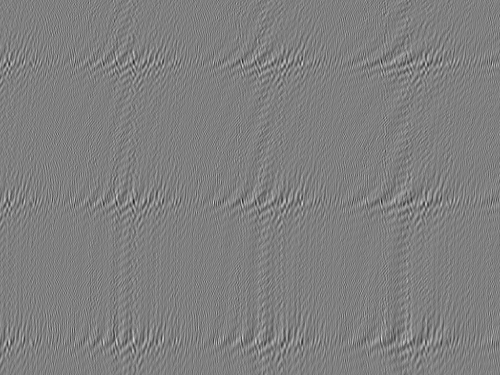
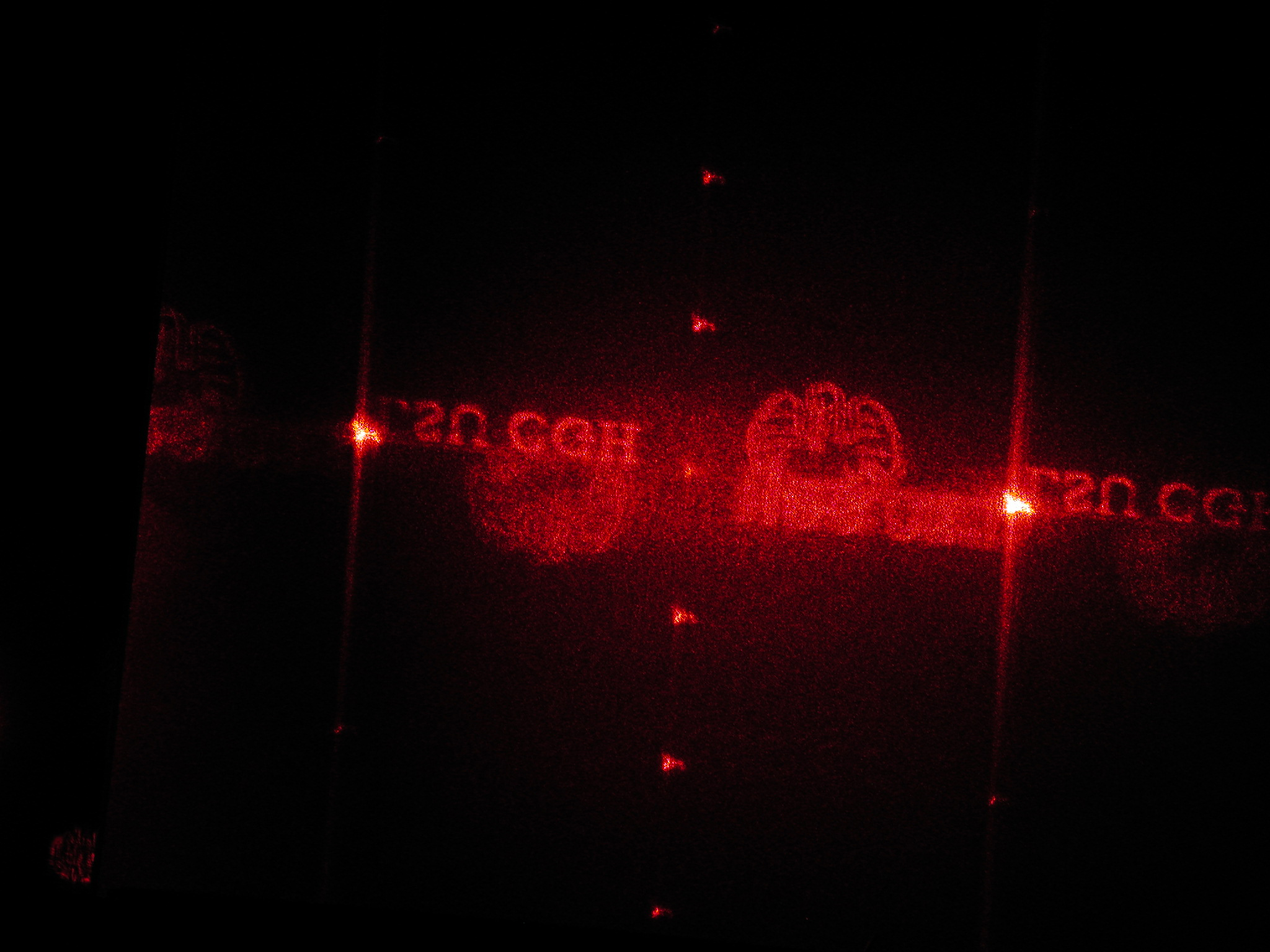
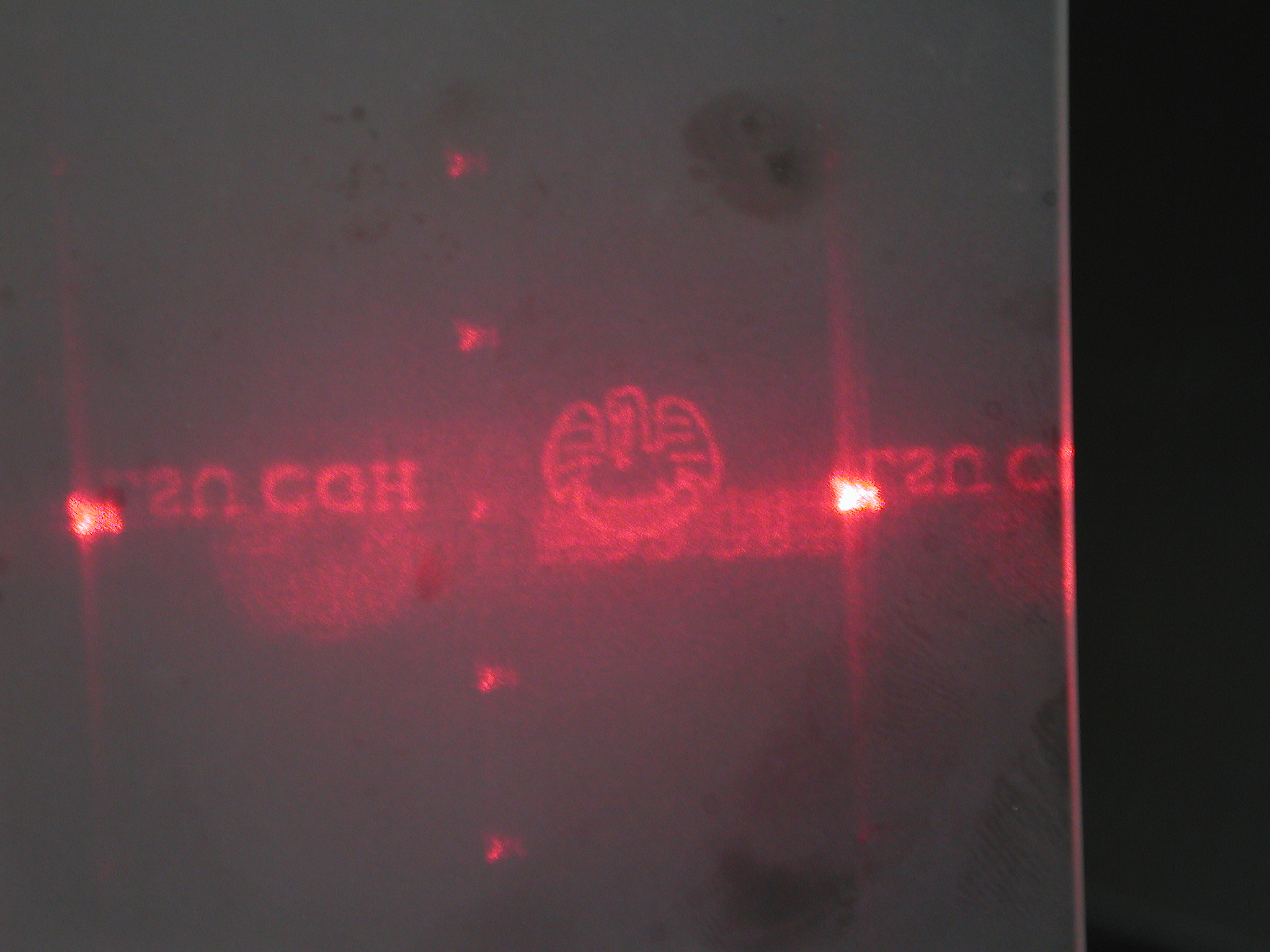
The objective is to create a fully three-dimensional (3D) ''rendering'' of the time-dependent surface of an object in 3-space, using efficiently calculated, two-dimensional digital holographic images. This will be accomplished by bouncing a monochromatic beam of light — the light source being, for example, an R, G, or B laser — off of a two-dimensional (2D) array of identical, small, rectangular mirrors such as the mirror configuration that provides the central functional element of Texas Instrument's DLP chip. Each mirror will be uniformly illuminated, but the brightness of the light that is incident on each mirror will, in general, vary from mirror to mirror. Ultimately, the desired 3D image will be constructed by adding together the diffraction patterns that are generated separately, but simultaneously, by all of the small mirrors in the array. | |||
==Slit Diffraction== | ==Slit Diffraction== | ||
| Line 145: | Line 159: | ||
</table> | </table> | ||
</div> | </div> | ||
where, | where (see the associated [[User:Tohline/Appendix/Ramblings/FourierSeries#Example_.232|''Example #2'' discussion]]), | ||
<div align="center"> | <div align="center"> | ||
<table border="0" cellpadding="5" align="center"> | <table border="0" cellpadding="5" align="center"> | ||
| Line 158: | Line 172: | ||
<td align="left"> | <td align="left"> | ||
<math>~\frac{\beta}{2c} \int_{-c}^c \cos\biggl( \frac{2\pi n \Delta y_1 x}{\lambda L_n} \biggr) dx</math> | <math>~\frac{\beta}{2c} \int_{-c}^c \cos\biggl( \frac{2\pi n \Delta y_1 x}{\lambda L_n} \biggr) dx</math> | ||
</td> | |||
<td align="center"> | |||
<math>~=</math> | |||
</td> | |||
<td align="left"> | |||
<math>~\beta \biggl[ | |||
\frac{\sin\theta_n }{\theta_n} | |||
\biggr] \, , | |||
</math> | |||
</td> | </td> | ||
</tr> | </tr> | ||
| Line 170: | Line 193: | ||
<td align="left"> | <td align="left"> | ||
<math>~-~\frac{\beta}{2c} \int_{-c}^c \sin\biggl( \frac{2\pi n \Delta y_1 x}{\lambda L_n} \biggr) dx</math> | <math>~-~\frac{\beta}{2c} \int_{-c}^c \sin\biggl( \frac{2\pi n \Delta y_1 x}{\lambda L_n} \biggr) dx</math> | ||
</td> | |||
<td align="center"> | |||
<math>~=</math> | |||
</td> | |||
<td align="left"> | |||
<math>~0\, ,</math> | |||
</td> | |||
</tr> | |||
<tr> | |||
<td align="right"> | |||
<math>~\theta_n</math> | |||
</td> | |||
<td align="center"> | |||
<math>~\equiv</math> | |||
</td> | |||
<td align="left"> | |||
<math>~\frac{2\pi n \Delta y_1 c}{\lambda L_n} \, .</math> | |||
</td> | |||
<td align="center"> | |||
| |||
</td> | |||
<td align="left"> | |||
| |||
</td> | </td> | ||
</tr> | </tr> | ||
Latest revision as of 01:55, 30 December 2017
CGH: Design Overview

|
|---|
| | Tiled Menu | Tables of Content | Banner Video | Tohline Home Page | |
Here we outline a research project that builds upon the extraordinary work of Huebschman, Manjuluri, & Garner (2003) titled, Dynamic holographic 3-D image projection.
 |
 |
 |
The objective is to create a fully three-dimensional (3D) rendering of the time-dependent surface of an object in 3-space, using efficiently calculated, two-dimensional digital holographic images. This will be accomplished by bouncing a monochromatic beam of light — the light source being, for example, an R, G, or B laser — off of a two-dimensional (2D) array of identical, small, rectangular mirrors such as the mirror configuration that provides the central functional element of Texas Instrument's DLP chip. Each mirror will be uniformly illuminated, but the brightness of the light that is incident on each mirror will, in general, vary from mirror to mirror. Ultimately, the desired 3D image will be constructed by adding together the diffraction patterns that are generated separately, but simultaneously, by all of the small mirrors in the array.
Slit Diffraction
Single Aperture
|
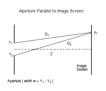
As has been detailed in an accompanying discussion, we examine, first, the amplitude (and phase) of light which, after passing through an aperture of width <math>~w = (Y_1 - Y_2) = 2c</math>, is incident on an image screen that is parallel to, and located a distance <math>~Z</math> from, the aperture. The amplitude at any location, <math>~y_1</math>, along the image screen is given by the expression,
|
<math>~A(y_1)</math> |
<math>~=</math> |
<math>~\sum_j \beta_j \biggl[ \cos\biggl(\frac{2\pi D_j}{\lambda} + \phi_j \biggr) + i \sin\biggl(\frac{2\pi D_j}{\lambda} + \phi_j \biggr) \biggr] \, , </math> |
where, <math>~\beta_j = \beta(Y_j)</math> is the specified brightness at each "j" point along the illuminated aperture,
|
<math>~D_j</math> |
<math>~=</math> |
<math>~ L \biggl[1 - \frac{2y_1 Y_j}{L^2} + \frac{Y_j^2}{L^2} \biggr]^{1 / 2} \, , </math> |
and,
|
<math>~L</math> |
<math>~\equiv</math> |
<math>~ [Z^2 + y_1^2 ]^{1 / 2} \, . </math> |
The green solid curves in Figures 2 & 3 of our accompanying, more detailed discussion display — for a fixed set of values of the parameter-pair, <math>~(\lambda, w)</math> — how the amplitude of the incident light, <math>~(A\cdot A^*)^{1 / 2}</math>, varies across an image screen that is placed at two different distances from the aperture.
Notice that, in the definition of <math>~D_j</math>, the expression inside the square brackets involves a term that depends quadratically on the dimensionless length scale, <math>~Y_j/L</math>, as well as a term that depends linearly on this ratio. As discussed below, our expression for the amplitude simplifies nicely in situations where the quadratic term can be ignored. (The red dotted curves in Figures 2 & 3 of our accompanying discussion illustrate how the image-screen diffraction pattern is altered as a result of this simplification.) Via a related simplification, we also will find that the various natural lengths of this problem can be related to one another via the expression,
|
<math>~y_1\biggr|_{1^\mathrm{st} \mathrm{fringe}} = \frac{L \Delta y_1}{c}</math> |
<math>~\approx</math> |
<math>~\frac{\lambda Z}{2c} \, .</math> |
CAUTION: Be sure that the "L" in these various expressions is, indeed, always the same quantity.
Simplifications
If we assume that everywhere along the aperture the phase <math>~\phi_j = 0</math> and if, furthermore, we assume that, for all <math>~j</math>,
<math>~\biggl| \frac{Y_j}{L}\biggr| \ll 1 \, ,</math>
we can drop the quadratic term in favor of the linear one in the above expression for <math>~D_j</math> and deduce that,
|
<math>~A(y_1)</math> |
<math>~\approx</math> |
<math>~e^{i2\pi L/\lambda} \sum_j \beta_j \biggl[ \cos\biggl(\frac{2\pi y_1 Y_j}{\lambda L} \biggr) - i \sin\biggl(\frac{2\pi y_1 Y_j}{\lambda L} \biggr) \biggr] \, . </math> |
Let's consider the case of a (single) aperture of width, <math>~w = 2c</math>, that is uniformly illuminated — that is, <math>~\beta</math> is independent of location across the aperture. If we allow the summation index, <math>~j</math>, to go to infinity, this (simplified) amplitude expression can be integrated to give, at various discrete <math>~(n)</math> locations along the image screen,
|
<math>~A(n \Delta y_1)</math> |
<math>~=</math> |
<math>~ e^{i2\pi L_n/\lambda} \biggl[ a_n + i b_n\biggr] \, , </math> |
where (see the associated Example #2 discussion),
|
<math>~a_n</math> |
<math>~=</math> |
<math>~\frac{\beta}{2c} \int_{-c}^c \cos\biggl( \frac{2\pi n \Delta y_1 x}{\lambda L_n} \biggr) dx</math> |
<math>~=</math> |
<math>~\beta \biggl[ \frac{\sin\theta_n }{\theta_n} \biggr] \, , </math> |
|
<math>~b_n</math> |
<math>~=</math> |
<math>~-~\frac{\beta}{2c} \int_{-c}^c \sin\biggl( \frac{2\pi n \Delta y_1 x}{\lambda L_n} \biggr) dx</math> |
<math>~=</math> |
<math>~0\, ,</math> |
|
<math>~\theta_n</math> |
<math>~\equiv</math> |
<math>~\frac{2\pi n \Delta y_1 c}{\lambda L_n} \, .</math> |
|
|
See Also
- Tohline, J. E., (2008) Computing in Science & Engineering, vol. 10, no. 4, pp. 84-85 — Where is My Digital Holographic Display? [ PDF ]
- Diffraction (Wikipedia)
- Various Google hits:
- Single Slit Diffraction (University of Tennessee, Knoxville)
- Diffraction from a Single Slit; Young's Experiment with Finite Slits (University of New South Wales, Sydney, Australia)
- Single Slit Diffraction Pattern of Light (University of British Columbia, Canada)
- Fraunhofer Single Slit (Georgia State University)

|
|---|
|
© 2014 - 2021 by Joel E. Tohline |
